Introduction
Little information is publicly known about Catherine L. Gibbon and her achievements. The legacy of her invention remains in tact because of the 1892 case file compiled by The Franklin Institute's Committee on Science and the Arts. Although details of Gibbon's life are sketchy, a glimpse of her scientific accomplishment is possible through exploration of the century-old documents found here.
Women and Transportation
Catherine L. Gibbon was born about 1851 in New York. (The name is sometimes seen as "Catharine," but appears in the case file and will be referenced throughout as "Catherine.") Though very few details about the woman and her life were uncovered in the researching of this case file, American women have been responsible for making improvements in travel for close to two centuries.
By the mid 1800s, Americans primarily traveled by walking, horse and carriage, steam ships, and canal boats. The era of the iron horse soon followed. Many women inventors contributed to improving safety and reducing noise pollution from trains. Mary I. Riggins developed a railway crossing gate, Eliza Murfey patented more than a dozen devices used to lubricate railroad-car axles and reduce the number of derailments, and Mary Walton created a system—which cradled the track in a wooden box lined with cotton and filled with sand—to reduce noise for elevated railroads in New York City. Walton later sold the rights to that system to the Metropolitan Railroad of New York City.
Keeping House
A woman working in the field of engineering in the 19th century was quite uncommon. Acknowledgement for her work was even less probable. Gibbon's improvements in street railway construction are noteworthy; her recognition in 1892 by a reputable Institution for those improvements is remarkable.
The United States 1880 Federal Census reveals some basic biographical information about Catherine Gibbon. In that year, she was 29 and living in Bethlehem, Albany, New York, with her husband Thomas H. Gibbon and three daughters: Sarah, Nancy, and Clara. Catherine's occupation on the census form is not listed as "engineer" or "inventor," but rather is recorded simply as "Keeping House."
Early Ways
Primitive railed roads called wagonways, consisting of wooden rails, were used in Germany as early as the 16th century. In the beginning of the modern railroad, wagonways allowed horse-drawn wagons and carts to move with greater ease than they did over dirt roads. By 1776, wooden wheels and rails were replaced with iron ones. Wagonways—and later "tramways"—spread throughout Europe. By the late 1780s, flanged wheels were designed, an important feature that carried over to later locomotives. The flange was a groove that allowed wheels a better grip on rails. Invention of the steam engine was vital to the invention of trains and the modern railroad.
A Good Foundation
The foundation of all good railroading is a good track, without which, no matter how superior all other appliances and equipment may be, there can be no success. Speed, safety and economy in operating expenses, all depend upon the character of the track.1
As the railroads expanded and more tracks were laid, there was much debate over what materials should be used in construction of the rails and how to use them efficiently. Poor building materials were susceptible to moisture retention from rainy or snowy weather conditions, contributing to a weakening of the track system. Weakened joints in the track were a particular problem; it was no easy task to hold the adjacent ends of two shallow rails or bars firmly together under the impact of the heavily-loaded wheels of a train. Weak joints potentially caused the track to impart a rolling or jumping motion to the train.
1Paine, Charles. "The Elements of Railroading."
Serious Defects
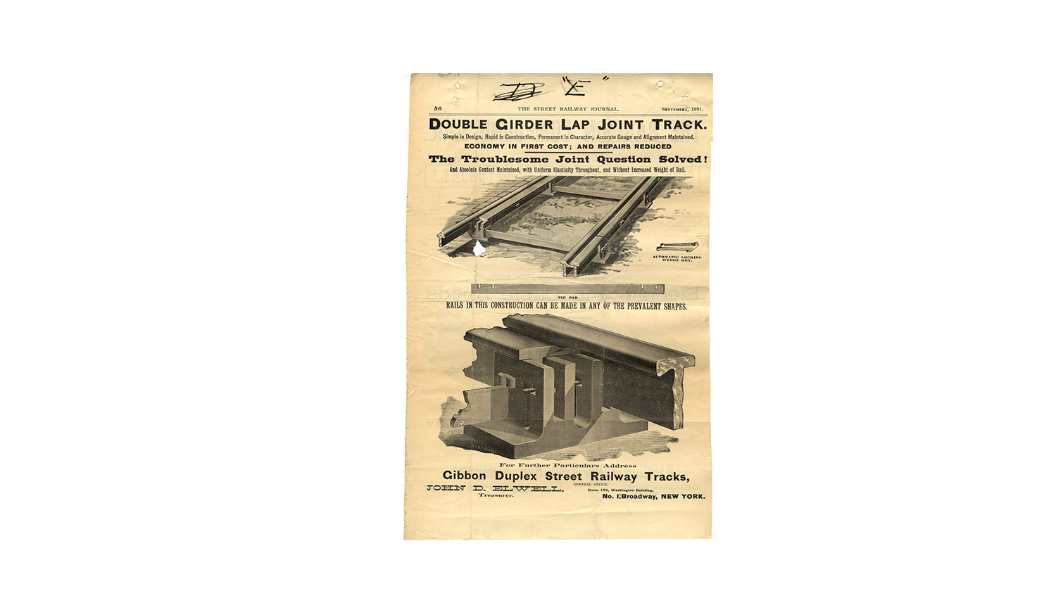
According to the Gibbon Duplex Street Railway Tracks Catalogue No. 1, none of the systems of railway track in use in the late 1800s were free from the "serious defect of "weak joints,"" despite the heaviness of the rails used in the construction of street railways. The Gibbon Double Girder Lap-Joint Track was invented to overcome these defective systems.
The Gibbon system saw an unreasonable number of metal parts assembled at each joint in other systems of the day, asserting that a well-known system pieced together no less than 28 separate pieces of metal at each joint and required 25 individual holes be made. The Gibbon Double Girder Lap-Joint Track boasted just six metal parts pieced at the semi-joints and eliminated the need for timber, spikes, bolts, and nuts entirely. Claiming that its construction cut down on the need for maintenance or repairs, the creators of the Gibbon system also marketed it as having a reasonable cost.
Throughout the Catalogue, the creators of the Gibbon system maintain that "The essence of good girder-rail construction is in lapping joints and doing away with "the splice bar fit.""
The Rail
The Gibbon track was composed of four main parts: the rail, the chair, the tie-bar, and the wedge.
The rail consisted of a head section and a flange section. The web of both sections, located directly under the center of the bearing surface, was mortised every two and one half feet of the rail to receive the wedge locks. Combined, the two sections created a complete rail; where head sections joined they were supported by solid flange section and where flange sections joined they were supported by solid head section. Through this series of underlapping and overlapping rails, a jointless track that evenly distributed load was formed.
The Chairs
There were two kinds of chairs, which could be constructed of any depth to suit the pavement: the joint chair, placed at each semi-joint of the rails, and the intermediate chair, placed at intervals between semi-joints. The vertical slots of the chairs received the web of the head and flange sections of the rails. The T slots received the tie bars and the wedges.
The Tie-Bar
A 2-inch-wide by 3/8 to 1/2-inch thick piece of steel, the tie-bar was slotted to any gauge desired near each end to receive the webs of the head and flange sections of the rail. The tie-bar locked the rails together, "perfectly and permanently gauging the track."
The Wedge
This piece was an automatic lock of true wedge shape with "harpoon" points. Once driven through the mortise holes in the chair and rail and over the tie-bar, the wedge locked the entire structure and itself in, binding the rails vertically while permitting them to expand and contract. The only way to force the wedge out was to compress the harpoon points with a tool and drive it out.
Laying Tracks
First, longitudinal trenches of appropriate width and lateral trenches for tie-bars were created. The metal chairs were then positioned in the longitudinal trenches, on a foundation of either stone or concrete, and the tie-bars were slipped through the chairs so that the slots in the tie-bars corresponded to the slots in the chairs. Connected by tie-rods, a pair of joint chairs was placed every fifteen feet. The intermediate chairs were placed every five feet.
Wooden templets that corresponded to the "web" of each section of rail were then placed longitudinally in the grooves of the chairs. Operation of these templets spaced the chairs and aligned and gauged the track. Next, the trench was filled with sand or fine concrete and tamped. Only then could the inner templet be removed and the girder of the flange section put in place, and the outer templet removed and the girder of the head section put in place, so that the head and flange sections formed a jointless track. Once two sections of rail were correctly positioned, the wedges were driven into place.
Advantages
The Gibbon Double Girder Lap-Joint Track system claimed ten advantages that are outlined below. Through correspondence with the Committee on Science and the Arts, it appears that the tenth claim, that of cost, was questioned. Thomas Gibbon and his consulting engineers offered further information, and asked the Committee to reconsider the tenth claim of superiority.
Advantages Claimed:
- The durableness and permanence of an all metal system.
- The smoothness and stability of a track absolutely free from weak joints
- Increased vertical and lateral strength with no increase of metal
- Freedom from torsional strain—the bearing surface being directly supported by the vertical webs
- Increased wearing capacity of head rail
- In renewal, the discarding of the worn portion only, and not the entire rail
- Perfect alignment and accurate gauge maintained, with required freedom for expansion and contraction
- Simplicity of construction which enables rapidity in track laying and a minimum disturbance of the public streets
- Maintenance of an absolute contact of metal, which obviates the necessity of "bonding joints" in electrical traction
- A reasonable first cost, and great reduction in track maintenance and repaire
Patented Tracks
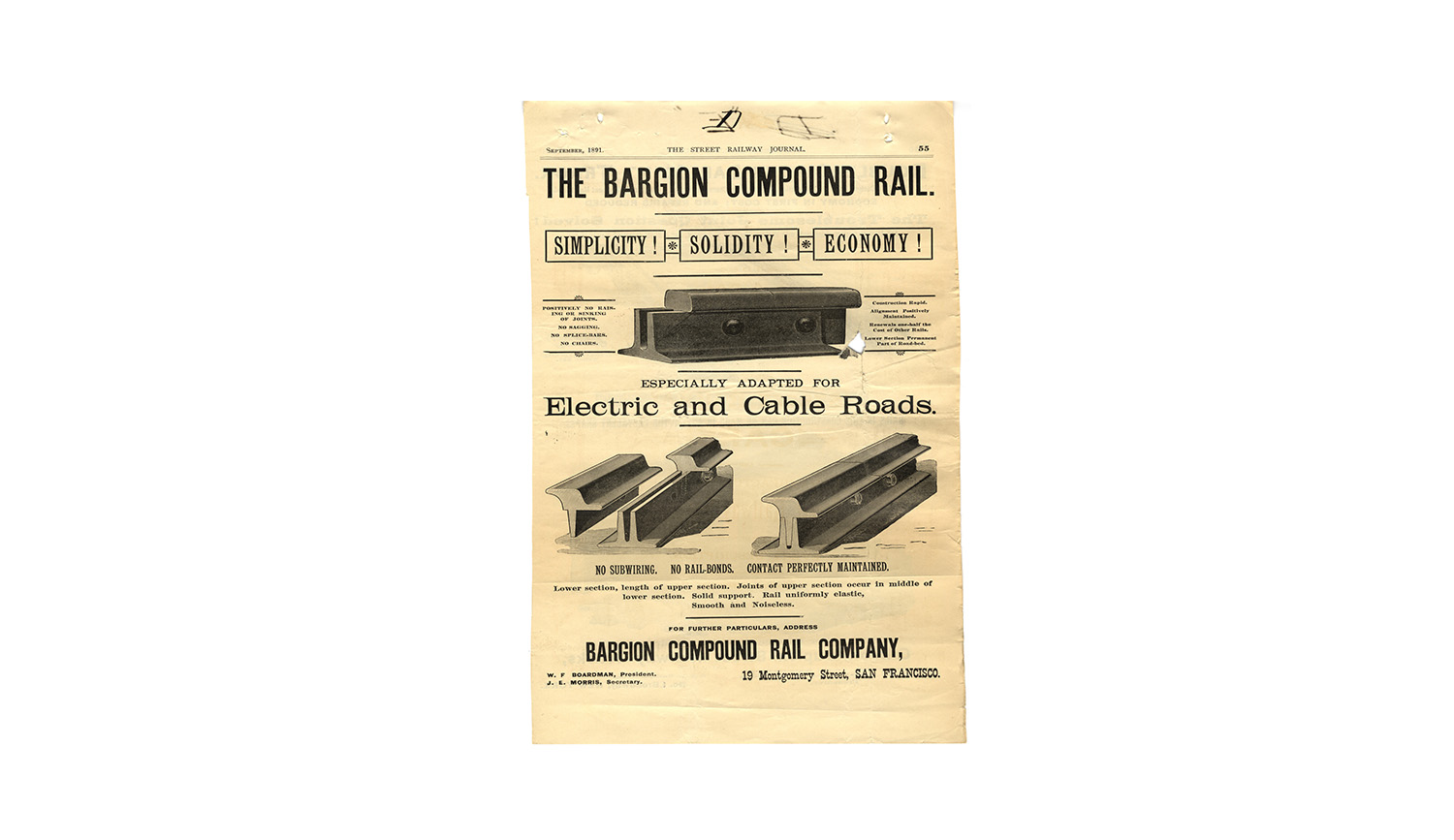
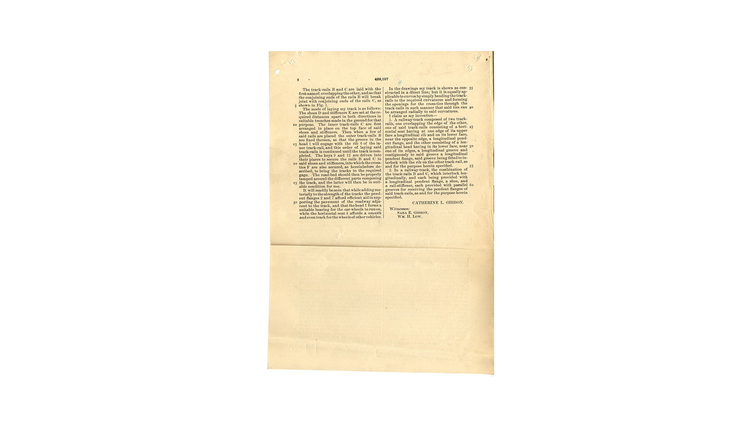
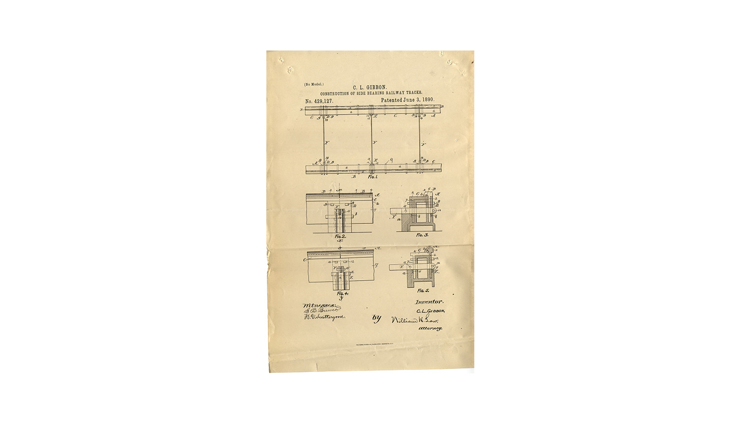
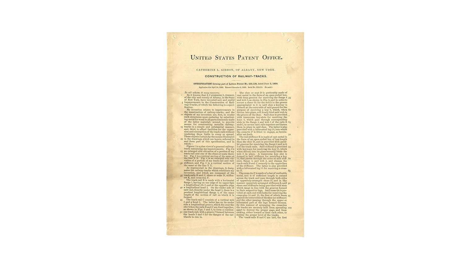
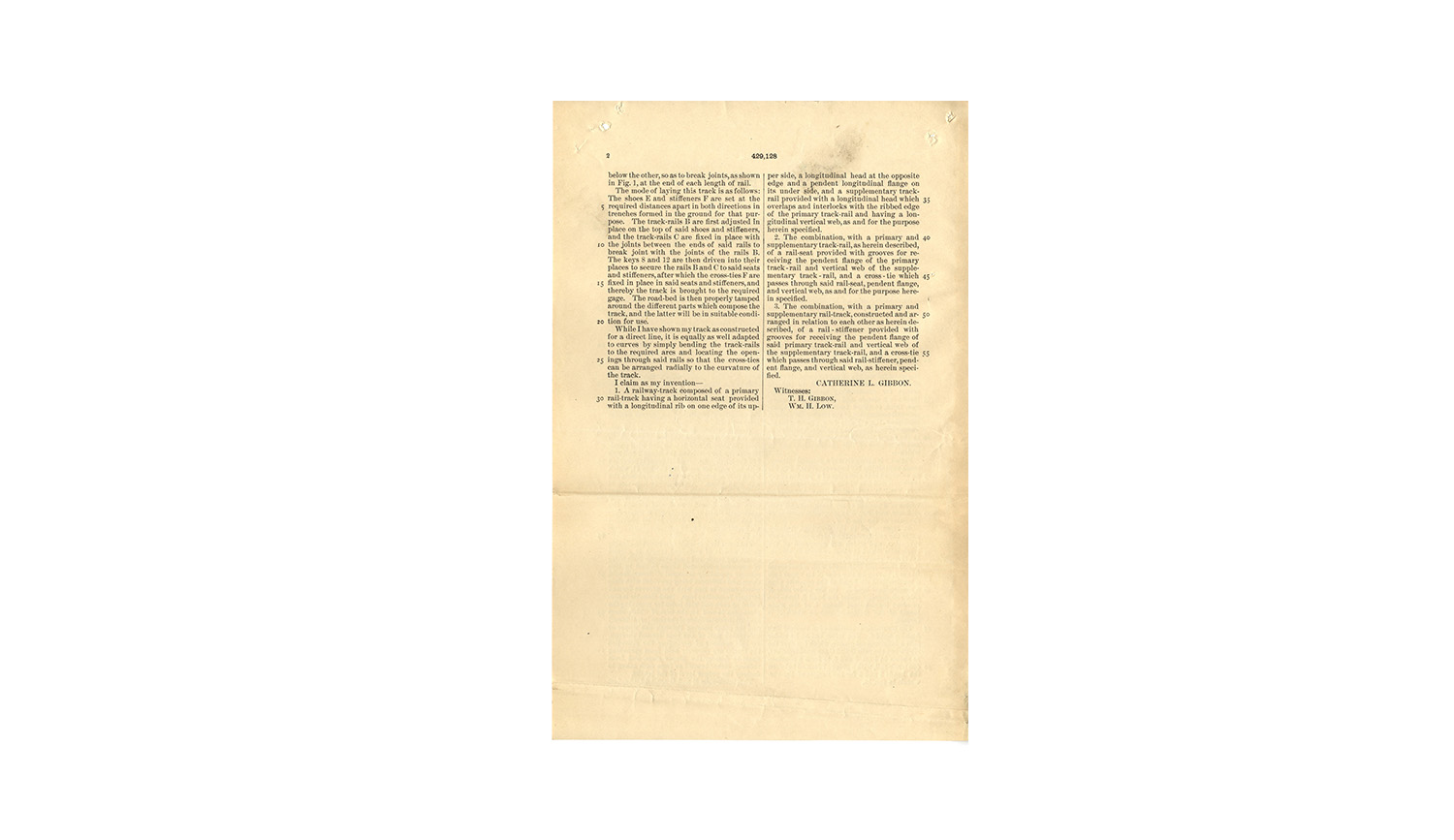
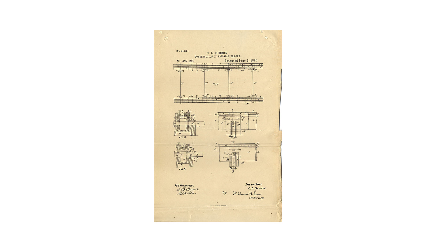
Two mechanical patents were issued to Catherine L. Gibbon by the U.S. Patent Office in Albany, New York, on June 3, 1890. One was for construction of side-bearing railway tracks (429,127) and one for construction of railway tracks (429,128). Two additional patents were issued jointly between Catherine and her husband, Thomas H. Gibbon on September 22, 1891, in New York, New York. The first was for construction of railroad tracks (459,780) and the second for compound rail for railway tracks (459,781).
Acknowledgement
Catherine L. Gibbon was awarded the John Scott Legacy Medal in 1892 for "Improvement in Street Railway Track Construction." The sub-Committee report, dated April 1 of that year, can be found below, as well as the Gibbon Duplex Street Railway Track Claims for Superiority. Two separate report covers appear at right.
The Catherine L. Gibbon presentation was made possible by support from The Barra Foundation and Unisys.

Read the Committee on Science and the Arts Report on Catherine L Gibbon’s Duplex Street Railway Track and their recommendation for John Scott Legacy Medal.